
MTP Fiber Cabling
I worked with MTP cables for the first time recently as part of a 40G Ethernet deployment. This was definitely a learning experience for me. There are a few aspects of MTP cabling that require some thought before you deploy it.
First and foremost is the polarity. An MTP cable is made up of 12x individual strands of fiber. Typical 40G Ethernet optics transmit on first 4x strands, and receive signals on the last 4x strands. The 4x “transmit” strands at one end need to end up at the “receive” connectors on the other end. In other words, the polarity of the cable has to be inverted between the two devices.
With the LC connectors that are typically used for 1G and 10G fiber cables, this isn’t a big deal. You can flip the two fiber strands on the LC connector easily to invert the polarity if needed. The MTP connectors however are fixed, you can’t change the ordering of the strands on the connector. There are two different ways you can invert the polarity of an MTP connection - using a coupler / bulkhead adapter, or using a “B” patch cable.
MTP couplers are simple plastic rectangles that hold two MTP connectors together.
Another issue with MTP device to pay attention to is that the genders of the connectors going in to the coupler matter. This was not initially obvious to me. One cable going in to an MTP coupler needs to have a male connector. The other cable must have a female connector. We initially only had cables with female connectors. They snapped into the coupler just fine, but would not work.
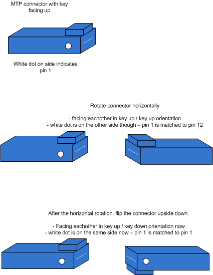
The other important factor to note about MTP couplers is that they can be either key-up to key-up, or key-up to key-down. MTP cables have a clip on the top of the connector. On a key-up to key-up coupler, the clips are pointed the same direction on both of the cables. On a key-up to key-down coupler, the clips are on opposite sides. This also effects the polarity of the signal. Key-up to key-up couplers invert polarity. Key-up to key-down couplers retain the original polarity. This was initially counter-intuitive to me. It made sense once I thought about it though. Here’s a diagram I made that helped me:
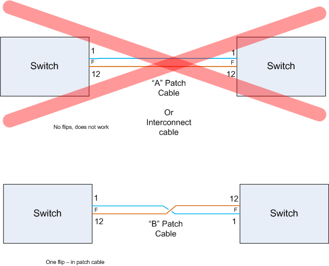
If you are using key-up to key-down couplers, you’ll need to use a “B” style patch cable at some point in the system to invert the polarity. (The “A” style MTP patch cable retains the original polarity - think of it as a straight through cable.)
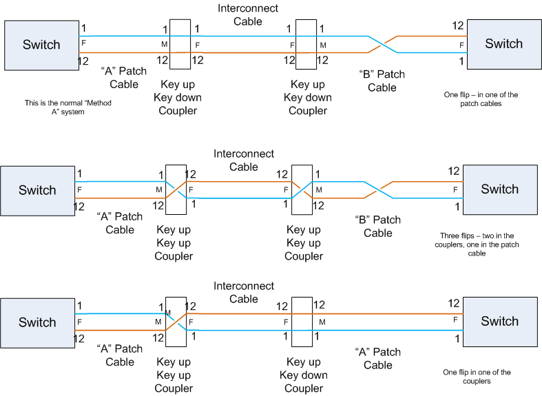
Here are some examples of what different cabling options for MTP look like. I feel like mapping this out helped me a lot. It took me a while to work through the details, but I think I have a much better understanding now. The recommended approach from what I understand is the “Method A” system, with two bulkheads. This wasn’t feasible in our environment though.
Options if No Bulkhead is being used:
Options if One Bulkhead is used:[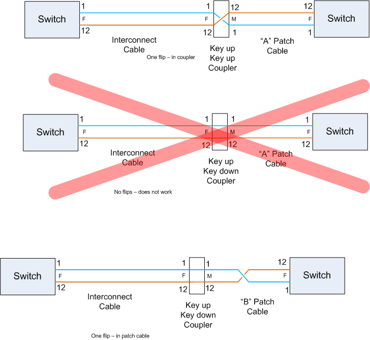
](/images/2013/06/one-bulkhead.png)
Options if Two Bulkheads are used:
So, using MTP cabling requires much more planning than you might have been able to get away with using LC connectors. Where possible, I would look at active optical cables for 40G connectivity instead of using QSFP+ optics and separate MTP cables. Active optical cables have the QSFP+ optics built in. So, you don’t have to worry about the polarity, gender, etc. You just plug the QSFP+ optic into each switch. Active optical cables are also cheaper than paying for QSFP+ optics themselves plus a separate cable. The biggest downside is that they typically can’t go as far.