
Data Center Server Access Topologies: Part 4, Uplinks
In this post I’ll briefly touch on some of the different ways access blocks can be connected up to the distribution layer in your data center.
Spanning Tree Topologies
I’ve outlined four different possible spanning tree topologies below. Realistically though, if you’re using spanning tree you probably should either do a traditional triangle topology, or possibly a loop free “inverted u” topology, if you’re OK with the caveat’s that come along with it.
Traditional Spanning Tree Topology
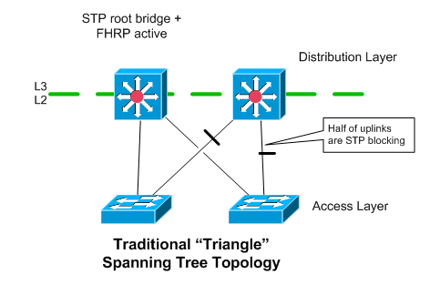
This uses separate VLAN trunks (potentially port-channels) from each access switch to both of the distribution layer switches.
Spanning tree is used, so only one of the uplinks on each access switch is forwarding traffic. If you need more upstream bandwidth, you’d have to make the uplinks port-channels.
Assuming you’re doing L3 at the distribution layer, you’ll generally want to align the STP roots with the device that owns the default gateway address (the active FHRP router). This helps make the traffic flow a little more efficient, and reduces the traffic that will flow over the VLAN trunk interconnecting the two distribution layer devices.
Advantages
-
Most common topology in existing data centers
-
If STP links are all costed properly, all “transit” traffic should flow through the distribution switches (the access switches won’t be providing “transit” for any devices that aren’t directly connected to them), even during most failure conditions.
Disadvantages
-
Half of the uplinks are blocked via Spanning Tree.
-
More ports required on the distribution layer devices than with a “Loop Free U” topology
-
East-west flows between different access switches have to flow up and then back down.
Square Loop Spanning Tree Topology
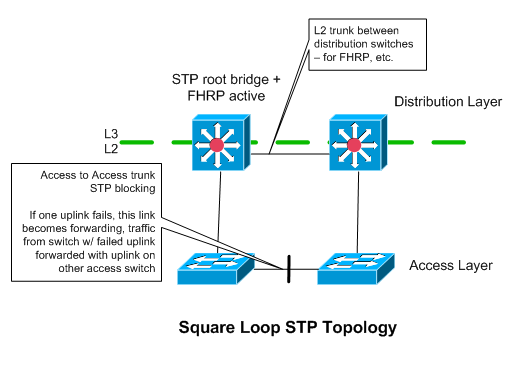
In this topology, each access switch has only a single L2 uplink to a single distribution layer device. Each pair of redundant access switches has a total of two uplinks - one to each distribution switch. The pair of access switches also have a L2 connection between themselves. This is used during a failure, and should have a high enough STP cost to ensure that Spanning Tree blocks it, as opposed to one of the uplinks to the distribution switches.
I’m not really sure why you would use this spanning tree topology in a data center. Two more uplinks in a data center (to make a triangle loop STP topology) are relatively cheap and easy to obtain.
Advantages
-
Fewer ports needed on distribution layer devices than with a triangle topology.
-
All uplinks to distribution layer are forwarding traffic (no STP blocking there).
Disadvantages
-
Still relies on spanning tree for failover
-
During uplink of distribution switch failure, one of the access switches in the pod handles transit traffic from the other one. This could impact the servers sitting behind the access switch that would otherwise still have good connectivity / be unaffected.
-
Less redundancy
Loop Free “U” Topology
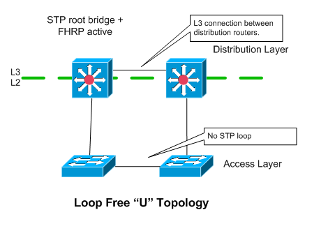
In this topology, each access switch only has a single uplink to a single distribution layer device. Access switches are “paired”, and have a L2 link interconnecting them to provide redundancy in case of uplink or distribution router failure.
Assuming you have multiple access switch blocks hanging off of the distribution layer, you would probably want to isolate each VLAN to a particular access pod, otherwise you end up having a loop.
Advantages
-
In theory this doesn’t rely on spanning tree
-
Fewer connections to distribution layer are needed
Disadvantages
-
Uplink failure results in access switches providing “transit” - so one uplink failure could affect the performance servers on the switch with the surviving
-
Some ugliness resulting because the distribution devices don’t have a direct L2 connection. So FHRP advertisements end up going through the access switches to be seen by the other distribution router.
Loop Free “Inverted U” Topology
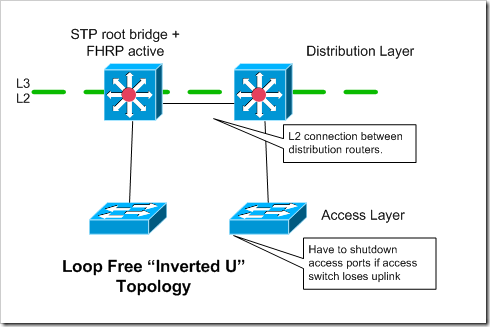
With an “inverted u” topology, each access switch has only a single, non-redundant, uplink. Access switches must be configured to shutdown their access ports if they lose their uplinks. Otherwise traffic from the servers will be black-holed. I’ve discussed this issue in a couple of my earlier access topology posts. All redundancy is handled at the server level - when the server chooses which connection to transmit out of. The access switches are not redundant in terms of their connectivity to the rest of the network.
This could be an OK option in a grid type environment that’s focused on cost, when redundancy is handled at a higher level - like through job scheduler software. That being said - you’re not saving much money by only having two uplinks for each access “pod” rather than four..and you’re giving up a ton of resiliency.
Advantages
-
Uses fewer ports on distribution layer devices, and on the access layer devices
-
Doesn’t rely on spanning tree
Disadvantages
-
Not appropriate for servers with only a single connection.
-
Not an option for most environments because of the lack of redundancy at the network level
Spanning Tree Alternatives
Cisco VSS

Cisco’s VSS solution turns two Catalyst 6500 or 4500’s into a VSS pair, that are managed as and act like a single switch. So, the members of a port-channel can be split across both of the switches in the VSS pair. If you are using VSS at the distribution layer, each of your access switches can have a port-channel with two members, one going to each of the switches in the VSS pair. From the perspective of the access switches, its uplink is just a normal port-channel. It doesn’t need to know anything about VSS.
Advantages
-
Quick failover times using port-channels. No spanning tree or IGP reconvergence is needed when a link fails
-
Doesn’t rely on spanning tree. Since port-channels are being used, all of the uplinks are in a forwarding state.
- No FHRP needed
Disadvantages
-
The VSS pair has a single management / control plane.
-
Limited vendor / platform support - Only supported on Cisco Catalyst 6500’s / 4500’s.
Cisco VPC
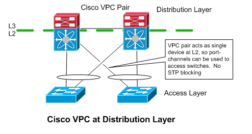
Like VSS, Cisco’s VPC allows you to have port-channels that terminate on different distribution layer switches (Nexus 7000 / 5000 / 3000’s). It’s implementation is different though. The switches in the VPC pair are less tightly coupled - they each have their own management and control planes. From a L2 perspective, the Nexus devices act as a single device, in that they appear as a single device to spanning tree, at the end of a port-channel. From a L3 perspective though, the Nexus devices are completely separate.
Like with VSS, the access switches are oblivious to VPC. They just see a normal port-channel. Because the devices in the VPC pair have separate control planes, an FHRP is still needed between them, however (at least with HSRP), it will be used in an active/active configuration. This is necessary to prevent a lot of traffic from going across “peer link” between the two VPC devices.
The access layer switches will just use normal port-channel hashing to decide which link to send traffic over. So, roughly half of the of the traffic coming up from the access switches would end up at the “wrong” distribution router if only one of them were active for the default gateway address. All of that traffic would then have to be sent over the peer link to get to the router that was “active” for the FHRP / default gateway address.
Advantages
-
Quick failover times with port-channels.
-
No spanning tree / blocking
-
(Mostly) separate management / control planes on distribution routers.this makes me more comfortable
Disadvantages
- Limited platform support - only on Cisco Nexus gear
TRILL / FabricPath / VCS
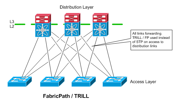
TRILL is a relatively new technology that is starting to gain some traction, and looks like it make become pretty common in the future. TRILL completely eliminates the use of spanning tree in the access to distribution layer connectivity. You still will likely want to run STP on the access switches though to protect against loops that could occur between access ports.
FabricPath and TRILL are Cisco and Brocade’s implementations of TRILL, respectively. They are not interoperable with eachother or with the TRILL standard, though it sounds like the vendors are open to supporting standards based TRILL in the future if it develops further to their liking.
I’ve not seen TRILL or FabricPath actually used. Once these technologies mature a little more, I think there may be a lot more adoption of them. It looks like they have a lot to offer, and that they can definitely change the game when looking at how to build data center networks.
Advantages
-
A lot of potential, can scale out a lot more than VSS or VPC
-
Allows a subnet to extend beyond a single access block
-
All links are forwarding.no blocking due to spanning tree. Also appears like it is safer than spanning tree
-
Simple configuration
-
May be able to handle east-west traffic flows between servers better, depending on how you connect your FabricPath devices
Disadvantages
-
Somewhat new, not deployed commonly, so people are less familiar with it
-
Limited platform support - and some vendors require additional expensive licenses to use it
-
Standards still in flux, not a whole lot of interoperability yet
Layer 3 to Access Layer
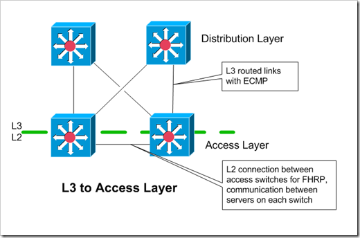
When doing Layer 3 (routing) to the access layer, each access block is it’s own self contained layer 2 domain. Instead of having L2 trunk uplinks to the distribution layer, the access switches have point-to-point routed links to the distribution layer. The access and distribution layer devices peer over an IGP. ECMP (equal cost multi-path) can be used to distribute the flows over different links.
My diagram above shows two uplinks for each access layer device. In theory, you could have only a single L3 uplink on each of the access switches. This complicates things though - you’d either have to have L3 peering between the two access layer devices, or make sure that the device owning the default gateway / FHRP addresses will give up ownership if it loses its uplink. With the first option, if the switch owning the shared FHRP address loses it’s L3 uplink, it will continue to accept traffic for the default gateway’s address. Once the IGP reconverges though, that traffic would be forwarded across to it’s peer access switch/router, and then up to the distribution layer. With the second option, the switch that loses it’s uplink should let the owner switch take over ownership of the shared FHRP addresses.so that traffic destined to the rest of the network would never hit the switch without an uplink in the first place.
VLAN’s / subnets stay within each access block. This could change in the future, with overlay technologies like VXLAN, that overlay a single subnet over routed connections.
Advantages
-
Limited L2 failure domains
-
IGP’s are more scalable and safer than spanning tree, can have lower failover times
Disadvantages
-
VLAN limited to single access block
-
Possibly additional complexity from having SVI’s spread out over more devices in the data center.
Closing
This post concludes my series of posts on data center access layer technologies. From these articles four articles, I hope you can see that there are a lot of options out there for building the access layer within a data center. In most of the cases, no one option is universally better than all of the others. There are a lot of trade-offs to make, depending on what your goals are. If you have any questions - please let me know!
Here are the final links to all four of the articles in my Data Center Server Access series of posts: Data Center Server Access Topologies: Part 1, Logical Interface Config on Servers
Data Center Server Access Topologies: Part 2, Cabling Topology
Data Center Server Access Topologies: Part 3, Switch Technologies